Wednesday, March 31, 2010

Mar.29-31Learning building, design and events

For Tutorial 2:  Building the Car Wash
Using parts of a LEGO forklift construction to learn how to make something that goes up and down with LEGOs. Mainly learned how to make a track and how far up & down a track works without tilting to 1 side or the other. Next is learning the ultrasound sensor.

Graphical OO SW design  mapped to real objects:
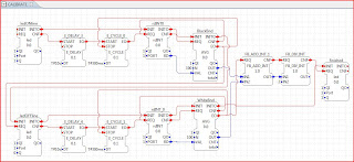
Still working on using just 1 light sensor for line follower in 4diac. How to use just 1 light sensor FB mapped to the actual 1 light sensor to read the light sensor to 4 steps:
  • calibrate on the line color
  • calibrate off the line color
  • follow the line
  • find line. 
then "repeat" for a follow the line application with 3 light sensors. 
Want a clean design - currently still looks like spaghetti.
Current direction: Use E_DEMUX to direct  the read output to the current step.

Whether it can be implemented similar to the behavior programming design used/described in Lejos documentation - is currently still an open question.

Port mapping, so an application can't say there are 2 sensors on the same sensor port.  That should be handled during INITs.

Created an Events palette overview to understand what events are available to use.  Everyone starting out seems to ask the same/similar questions.

But what is the basic FB E_LDU (Event-driven Workpiece Load/Unload Model)? It has    2 algorithms, but no ecc? 

Friday, March 26, 2010

Mar.26& Apr.2 Blinky with LtSensor.led etc

Using LEGO HW:
1. Create and export FB types via normal way:
  • 4diac-ide Types
  • export to Forte using 0.4 export filter
  • edit C++ code for SI FBs 
2.  openocd-FLASH.bat
3.  openocd.bat
     know finished when:
  • the LMS boot blinking finished 
  • the PC sounds indicate new HW connected
4.  run from eclipse java
5.  4diac-ide deployment (check and download)
     (not launch!)


Tested and working with:
  • Alex's blinky unchanged
  • Alex's blinky with shorter delay times
  • In Alex's System: New Application: Test1LedOff with 1 LMS_LED (discovered 1=turn off) 
  • In LegoHW:  OffLed changed new LtSensor.led FB so 0=turn off
Next:
  • In LegoHW: in LtSensor.led FB use input PORT
  • Note: #define macros are used to shorten for hw access. The macros refer to lower level macros. The highest level macro used had port# in its name, so used #define macro 1 level down where the port # appears as a number.

Currently getting:

end Mar.26 
Error: Vref too low. Check Target Power
Even after trying: 
  • a different fully charged battery pack  
  • leaving charger plugged in 
but after continued tries, it appeared to be get further before failing - so will try again after plugged in a while.

Apr.2 works: 
Suspect problem was the PC was confused if LMS is USB or something else.
Next time problem occurs need to try openocd-flash.bat after each of the following:
(not sure which one cleared the problem):
  • Plugged in a USB memory stick and disconnected it.
  • Unplugged/plugged in the LMS USB cable and went to control panel to install new HW. When clicked on it - said this id is not autorized.
  • Tried openocd-flash.bat and it worked.
The broken pipe problem occurred when Alex was showing me what to do. He also had to try various things to get it to work again. Did we plug in an USB stick at some point to save something? Maybe.


Important Design Problem: Use 1 instantiation when only 1 physical object or when reading or writing you have to be aware of state changes.

Seems obvious, but easy to use  more when "hidden" in a Composite FB
Ex: an application that uses composite FB - for example lineboundary or calibrate before line1 (very simple line follower).

Tuesday, March 23, 2010

Mar.23-26 Notes from Alex on eCos/LegoHW set-up

note: lms= Lego Mindstorms

when openocd_flash doesn't work.

   under programs Atmel /Sam-ba flash

In C++ Eclipse:
·       setup_lms  creates the makefiles
·       all (see  makefile.am for list of files ) (just normal make all)
        ·       compiles and links to ecos
        ·       the output file is forte. (no ext)

From Desktop:
openocd_flash.bat
·        first creates the forte.bin
·        It outputs size of forte.bin
·        It flashes forte.bin to lms via jtag. (with the available FBs)
 
After flashing, the program does not run, it’s halted.
openocd.bat resets the lms and starts running.

In java Eclipse - run

open 4diac-ide deployment: 
·       check system with application
·       download (FB instantiations that make up the application)
·       application should run


Optional debugging with  gdb
·       start arm-elf-insight from cygwin
in gdb

·       Open forte using default
·       connect via Ethernet – localhost/3333

(where? details notes lost)
        ·        monitor reset
        ·        monitor halt
        ·       (usually did a 2nd reset?)
        ·       see GDB table for more commands
        ·       can only use 1 breakpoint at a time

        ·       openocd.bat (should already be running)

First Tasks:
Check Sensor HW outputs like:
GetButtonState() - buttons are 1,2,4,8 but which button is which
SetOutputPower(…) - from motor
etc.


Cmds from cygwin history:
cd events/
svn commit -m"solved issue in E_RS"

cd /cygdrive/c
whoami
login
 cd /cygdrive_ecos
cd /cygdrive/c
 cd sourceware_ecos
 cd 3/lego/blink_hal

make
make clean
svn
 arm-elf-insight
 arm-elf-size blink_hal
 cd ../d/AA_local/eclipseWork/forte_lms_neu/src/fblib/

Sunday, March 21, 2010

Mar.23 Calibrate as Composite FB + FindLine

Calibrate as a composite FB 
(currently exported code has casting problem)


LineBoundary - returns the average boundary between line and off-line light sensor values.
   It uses CALIBRATE1 composite FB


FindLine Application: sweeps left and right looking for line (10 degrees) 
   Currently keeps looking even if never finds line.

Mar.19 LegoHW types and apps

Lego HW types (1st try):

Line1 application: overly simple line follower - if black both motors forward, otherwise just 1 motor. Will only work in 1 direction.
 
Calibrate application: calculates the on-line (Black) and off-line (usually White) boundary.

Thursday, March 18, 2010

Mar. 18 LEGO HW and simulator

Light sensor on multiple targets:
HW:
LS in 4DIAC as (SIFB)  export
  • for LEGO HW: add HW calls to C++
  • for java simulation - use FBDK as described previously in blog
  • hide the subscribe (for motor publish) in composite block, then use FBDK for java
    • XML trick so stays SIFB in 4DIAC but is composite block for simulation:
      • add   use other composite block XML as example

Generalize Sensor Port : in C++

static const state TUINT32[5] = {0,23,28,29,30};


Then current need for JTAG can limit school examples, but simulation may help and show/teach how IEC61499 can be flexible.


Need to ask about trial runs so they actually happen so:
Trial Runs of the IEC61499 Tutorial: 
April 30 - Sprengergasse HTL : Line Follower Tutorial
Wien TGM HTL - in May(?) - some students come to TU ACIN lab Thursdays
?St.Pölten HTL - (update 17Mar.) contact is no longer director. Hopefully he will still answer.
?HTLs of TU Lehramt Informatik Profs (Gangster, )
?in Houston area

Wednesday, March 17, 2010

Mar.17 JTAG debugging and optimized eCos+forte

(raw) Notizen Erklärung von Alex (to be organized / cleaned-up)


D:/AA_local/Dominik/pfade .txt = beschriebt was ist wo

Configuration downloaded in 4DIAC

Flashes = download O/s=eCos+FORTE+appl in 61499


Bei make all broken pipe – retry

If still doesn’t work in cygwin … see brokenpipe.jpg


Lms= lego mindstorms

lmsmain


Part of Gnuarm toolchain:

Start in cygwin:

arm-elf-insight used for debugging  connects über port 3333

see copied sheet and gdb-intro.pdf

monitor reset

monitor halt

monitor reset

delete – to clear breakpts


winmerge tool

lego_nxt_hw_dev_kit p.27 sensor diagrams


Tuesday, March 16, 2010

**March 16 Simulator + Lego HW with eCos+

Line Follower Simulator - using sub-applications seems to have destroyed what I had - which was simulated polling reading the light sensor using a slider. With I/O to verify/simulate reaction, the application was cluttered with Function Blocks not needed for the application using Lego HW.


17 Mar.Update - Workspace is still ok, except ReadLightValue simulator.Havn't tried to flatten to subapps.

     Dual Bot V2 document update in Wiki:
    Improvements 
    - not back heavy so doesn't almost tip over in curves
    - light sensors can easily to moved up

    4DIAC 
    error log in .metadata in workspace
    problem viewing system configuration for device with readLight application with subapps
    questions:
    Service Sequence - in SI FB type - delete works fine, add adds but can't rename it

    Lego HW with eCos
    goal: create SI type 4DIAC FBs for each sensor + motors 


    SI types / interfaces created so far in 4diac:
    shutdown; ltsensor.led; ltsensor.rd; touch; motor.basic


    HW Interface Functions:
    cyg_uint32 SetInputPower(cyg_uint32 pa_nInputPort, cyg_uint32 pa_nPowerType);
    cyg_uint32 SetOutputPower(cyg_uint32 pa_nOutputPort, 
                              cyg_int32  pa_nPercent,  
                              cyg_int32 pa_brake);
    cyg_uint32 SetSambaMode(void);
    cyg_uint32 SetShutdownMode(void);
    cyg_uint32 GetInputPower(cyg_uint32 pa_nInputPort);
    cyg_int32  GetOutputPower(cyg_uint32 pa_nOutputPort);
    cyg_uint32 GetBrakeMode(cyg_uint32 pa_nOutputPort);
    externC cyg_uint32 InitAVR(void);
    cyg_uint32 GetButtonState(void);
    cyg_uint32 GetBatteryVoltage(void);
    cyg_uint32 GetFirmwareVersion(void);
    cyg_uint32 GetAccupack(void);
    cyg_uint32 GetSensorState(cyg_uint32 pa_nInputPort);
    cyg_int32  ReceiveFromAVR(void);
    cyg_uint32 SendToAVR(void); 

    ARM HW info 
    annotated logic part of blinker cpp from Alois
    Is zur zeit so programmiert dass es nur in 1 sensor port geht. Für die anderen mußt du es wie folgt an passen:
     
    #27. PIO   Parallel
    Portpins für LMS_LED
    Nxt-ports
    Port-pins
    1
    PA23 (DIGIA0)
    2
    PA28 (DIGIB0)
    3
    PA29 (DIGIC0)
    4
    PA30 (DIGID0)
    Also see p.65 in LEGO_MINDSTORMS_TUTORIAL.pdf

    ref.s are to AT91 ARM HW pdf


     switch(pa_nEIID){
        case scm_nEventINITID:
          if(true == QI){
            HAL_WRITE_UINT32(AT91_PMC+AT91_PMC_PCER, AT91_PMC_PCER_PIOA); // enable parallel io-controller clock and power

    PMC = Power Mgt Cntlr under advanced power mgt in doc
    PCER = Power cntl enable Register
    PIOA = PIO port A= PA  (there is also a port B)
    see Table 27-2 for more abbrv.s
    27.6.10 / 11 PIO Cntlr Set & Clear Output Data Reg (PIO_CODR /PIO_SODR)

    #include // from eCos has constants and HAL_WRITE (hw abstraction layer)


    ....

            HAL_WRITE_UINT32(AT91_PIOA+AT91_PIO_IDR, (1<
            HAL_WRITE_UINT32(AT91_PIOA+AT91_PIO_OER, (1<
            HAL_WRITE_UINT32(AT91_PIOA+AT91_PIO_PER, (1<
            HAL_WRITE_UINT32(AT91_PIOA+AT91_PIO_SODR, (1<
          }
          sendOutputEvent(scm_nEventINITOID);
          break;
        case scm_nEventREQID:
          if(true == QI){
            if(true == Q){
              HAL_WRITE_UINT32(AT91_PIOA+AT91_PIO_CODR, (1<
            }
            else{
              HAL_WRITE_UINT32(AT91_PIOA+AT91_PIO_SODR, (1<
            }
          }
          sendOutputEvent(scm_nEventCNFID);
          break;

    Need for Ultrasound sensor:
    Lejos source code  http://lejos.svn.sourceforge.net/viewvc/lejos/

    Monday, March 15, 2010

    Mar.15 Setting uploop back device

    Lets you use your localhost network under windows

    Control Panel/ Hardware and Sound /Device Manager 
      > PC-NAME
         > Rt Click/ choose Add Lecacy Device 
             > NEXT / Install the HW ...manually select from list /select network adapter 
                >NEXT/ Microsoft (rt) 
                    > Microsoft Loopback Adapter / NEXT until Finish
    Was told to turn off wireless, but seems to work for me with it on.
    Firewall may ask questions when the loopback device is used.


    Tuesday, March 9, 2010

    Mar.9 4diac UI Notes

    In  4DIAC :
    To move the connectors so more readable:
      Extras / Preferences Default Router drop-down: Adjustable Router
      then when a connector is clicked on, a point is available for adjusting the location.
    Sub-application in 4diac: rt click / new sub-application
    Interface allows only the actual inputs/outputs used to show by  unchecking the other events & variables.

    [switching to math for the rest of the week]

    Monday, March 8, 2010

    *Tutorial 3: Assembly line Notes

    Idea:
    Presence Sensor (light, distance,..) tells a color sensor something is coming in x ms 
    Color Sensor application tells the Reject application if something is coming in x ms.

    Need a buffer between sensor applications.

    Mar.8 Line Follower Designs

    Common Designs:
    • OO sequential - in for loop read light sensor and react to state
    • behavior programming - an arbitrator checks in priority order defined behaviors, if their condition is true. The first behavior with a true condition is performed.  Ex: Online? go forward
    Behavior programming seems to fit into the design patterns:
    • observer pattern
    • publish/subscribe pattern
    which is used in 4DIAC network pallete as implemented by FBDK.
    Background Info: Design Patterns in the IEC 61499 Architecture 

    Sunday, March 7, 2010

    Mar.8 IEC 61499 Overview notes

    IEC61499 (notes for an overview for tutorial)  
    (notes from:    Want to switch Lewis quotes to quotes from offical standand - if understandable)
    -L= Lewis : Modelling control systems using IEC 61499, pp.22-
    - 4DIAC 
    )
    FB = Function Block 
    Main focus: model the behaviour of FBs within each resource.p.24 L
    • System Model "defines the relationship between communicating devices and applications." p.22 L
      • has application(s)
      • has device(s)
    • Device Model
      • has resource(s) (similiar to 61131-3)
      • "load and unloads distributed applications without disturbing existing applications" via management services
      • "has a process interface to exchange data via external networks with resources in remote devices." p.23 L
      • has a communication interface(outside of 61499) that provides communications services for resources to exchange data via external networks with resources in remote devices." p.23 L
      • has fragments of FB networks
    • Resource Model - "provides facilities and services to support the execution of one or more FBs application fragments."p.24 L
      • provides interfaces via Service Interface (SI) FBs
        •  to the communications systems (in 4DIAC FBs in netwk palette)
        •  to the 'device specific processes'."p.24 L (via SI FBs)
      •  supports independent operation It can be: loaded, configured, started, stopped L p.24
      •  [coordination of (different) resources when starting an application not yet addressed] L p.24
    •  Application Model - a network of interconnect FBs, linked by events and data flows.L p.25
      • can be fragmented and distributed over many resources (what is "fragmented"? into FBs?)
      • can have sub-applications (are they supported in 4DIAC?) 
    • Function Block
      • "allocated to a resource with interconnected devices."p.24 Lewis book
      • has in / out 
        • events and 
        • data
      • Types 4diac
        • Simple (? - not supported in 4diac)
        • Basic
        • Composite
        • Service Interface (SI) "provide a link between FBs and resource interfaces"L p.24 in 4DIAC via code added to the C++ code generated from the 61499 XML.
        • Adapter (? - not supported in 4diac)
    Differences btw. 61131-3 and 61499
    • Platforms and tools can't interoperate 4DIAC_Initiative.pdf p.5

    Friday, March 5, 2010

    Mar.5 for loop in IEC 61499

    FB experiments: for loop in IEC 61499


    Wednesday, March 3, 2010

    Mar. 4 Wiki start and Line Follower Simulator

    Line Follower 
    dual-motor-bot construction instructions

    Wiki:
    Changed Logo to new hopefully better quality logo.
    Added basic / linefollower construction links 
    *LEGO NXT Robot construction links entry made this very easy
    Blog documentation is making creating the actual tutorial easier


    Line Follower Simulator
    Averaging of just one "color"  (black) of light calibrator. This needs to be split up into a setPort and calibrate1Color FBs.


    Open Question
    If QI=1 then execute FB, 
    else 
    QI=0 ignore EVENTS
    Where is this documented? 
    In book QI/QO are input/output status. 

    Mar.3 Line Follower Simulation start

    The line follower uses only 1 device, so it should able to be modeled as 1 device. The simulated model will use different types of FBs. Basic and composite FBs must be added to some IEC 61499 RTE. The choices are FORTE or FBRT. Since the HMI FBs used for simulation are FBRT, if FORTE is used, then PUBLISH and SUBSCRIBE FBs must be used. This causes unnecessary complexity sending events between FBs on the 2 "devices". 

    So the simulation will develop the application and FB types in 4DIAC, but will add the FBs to FBRT for now. Simulation testing will also be done via 4DIAC. Since the FBs use Structured Text FORTE, they can also be used  for the real (ST) Lego Line Follower under eCos  without changes, except for direct Lego HW  I/O (Sensors, Motors, possibly the Display). Only FORTE will be running under eCos. So the real Lego line follower will need/use FORTE.


    Simulation:
    1. 4DIAC: Develop Application and FB Types
    2. FBDK editor parse: Check for basic and composite FB errors    
      (no Structured Text error checks currently in 4DIAC?)
    3. FBDK editor save as: 
      • Converts the updated XML to Java class (fb.rt.fbTypeGroupName)
      • Compiles to Java classes in FBDK
    4. 4DIAC: Add fbTypeGroupName to FBRT preferences
    5. 4DIAC: Add new FBs where needed in application
    6. 4DIAC: Test via Deployment of FBRT in 4DIAC